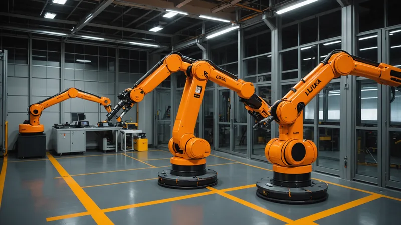
KUKA and Universal Robots are common partners in mixed-vendor cells. KUKA for the heavy industrial work, UR cobots for the human-adjacent or fine-dexterity tasks that the KUKA arm is not optimized for. In principle they complement each other well. In practice the commissioning involves three failure modes that appear repeatedly, each of which cost at least a full week the first time we encountered it. Here they are in detail.
Mistake 1: Assuming the KUKA RSI Cycle Time and UR RTDE Cycle Time Are Compatible
KUKA RSI (Robot Sensor Interface) runs at a fixed cycle time that you configure in the KRL program: typically 4ms or 12ms. This is the interval at which the KUKA controller sends UDP packets to the RSI client and expects responses. Universal Robots RTDE (Real-Time Data Exchange) runs at up to 500Hz, which is 2ms per cycle. So RSI and RTDE operate at different cycle rates, and if you are using both as inputs to an orchestration layer or PLC that needs to correlate state data from both robots, you have two asynchronous time series that need to be aligned.
The mistake is assuming this alignment is trivial. The UR RTDE data arrives at 2ms intervals; the KUKA RSI data arrives at 4ms or 12ms intervals. If you timestamp both streams on receipt and try to correlate state at a common sample time, you will see apparent discontinuities in the KUKA state that are actually artifacts of the interpolation between RSI packets. For position data, this matters mostly for post-hoc analysis. For state transitions, it matters in real time: a KUKA "ready" signal that arrives at 12ms resolution looks continuous in KUKA's own interface but appears as a step function with 12ms granularity when correlated with UR data at 2ms resolution.
The fix is to design the handoff coordination explicitly around the slower cycle time. If KUKA RSI runs at 12ms, the handoff coordination logic should run at 12ms or slower, not at 2ms. The UR side should be configured to match the handoff coordination rate, not to run at its maximum rate. This sounds obvious written out, but the default is to start both at their maximum rates and then debug the coordination failures.
Mistake 2: Treating KUKA SafeOperation Zones and UR Safety Planes as Independent Systems
KUKA SafeOperation allows you to define monitored space zones that restrict the KUKA arm's workspace. Universal Robots has its own safety plane configuration that restricts the UR arm's workspace. Both are designed for single-robot safety; neither is designed to enforce shared exclusion zones between two robots from different vendors.
In a cell with a KUKA KR 60 and a UR10e sharing a central workspace, the engineers on the project we were brought into had configured safety zones on both robots independently. The KUKA safe zone excluded the UR arm's primary work area, and the UR safety planes excluded the KUKA arm's primary work area. Both configurations were correct in isolation. The problem was that neither system knew anything about the other: the KUKA safety zone does not know where the UR arm actually is, and the UR safety planes do not know where the KUKA arm is. The zones were designed to be geometrically exclusive by static layout, with the assumption that each robot stayed in its own zone.
That assumption broke when the process required the UR arm to approach the boundary of its zone (to pick a part from the handoff station), because the boundary was positioned assuming the KUKA arm would always be at its home position when the UR arm was at the handoff station. When the KUKA arm was delayed by an upstream process and was still moving toward home while the UR arm arrived at the handoff station, the UR arm's end effector entered a region that the static zone geometry had assumed was safe. No hard collision, but the safety scanner triggered because the UR arm was in a position that violated the overall cell safety plan.
The correct approach is to use a PLC-mediated zone arbitration system: the PLC maintains the authoritative state of which robot has permission to be in which zone, and each robot must request and receive permission before moving into a contested zone. Neither robot's onboard safety system needs to know about the other; they both defer to the PLC's zone authority. This requires explicit zone request/grant signaling between the PLC and each robot controller, which takes additional commissioning time, but it is the only approach that correctly handles the transient states.
Mistake 3: The RSI/RTDE Clock Drift Problem
The third mistake is more subtle and took us the longest to diagnose. Both KUKA RSI and UR RTDE are time-stamped by their respective controllers. The timestamps are generated by each controller's internal clock. These clocks are not synchronized unless you explicitly configure NTP or PTP synchronization on both controllers and the network switch between them.
Without clock synchronization, the KUKA and UR clocks drift relative to each other. The drift is slow, typically in the range of tens of milliseconds per hour, but in a system that ran continuously across shifts, we saw the clocks diverge by 200ms to 400ms over an eight-hour shift. When the orchestration layer was trying to correlate state data from both robots to reconstruct the timing of a cycle completion event, the clock drift introduced errors in the reconstructed timeline that made the cycle logs increasingly unreliable over the course of a shift.
The operational symptom was not obvious: cycle time reports were showing a gradual apparent increase in cycle time over the course of a shift, even though the actual physical cycle was not changing. The cycle time calculation depended on correlating KUKA RSI timestamps with UR RTDE timestamps, and the clock drift made later cycles appear longer than they were. The error accumulated slowly enough that it was not caught during the initial commissioning sessions (which typically ran for an hour or two), but it appeared clearly in production data after a few weeks.
The fix: configure NTP synchronization on both the KUKA KRC4 and the UR controller to a common NTP server on the factory network. The KUKA KRC4 supports NTP configuration in the KUKA System Software configuration interface. UR controllers support NTP via the system settings. With both synchronized to the same NTP server, clock drift is typically under 1ms per hour, which is negligible for the correlation use cases described above.
The Common Thread
All three of these failures share the same root: they are problems at the boundary between two systems that each work correctly in isolation. The KUKA RSI cycle time is fine for KUKA-only integration. The UR RTDE cycle time is fine for UR-only integration. The KUKA safety zones are correctly configured for KUKA. The UR safety planes are correctly configured for UR. Each clock is accurate on its own. The failures appear when the two systems are asked to coordinate, and the assumptions that made each system work in isolation are not compatible.
This is precisely why mixed-vendor commissioning requires explicit attention to the boundary layer between systems, not just to each system individually. A checklist that verifies each robot controller is correctly configured in isolation will not catch any of these three failures. The verification needs to be at the interaction level: what data does each system produce, how does the other system consume it, and what are the failure modes if that consumption is slightly off?
Read next: Why Mixed-Vendor Workcells Break Down at the Handoff Layer