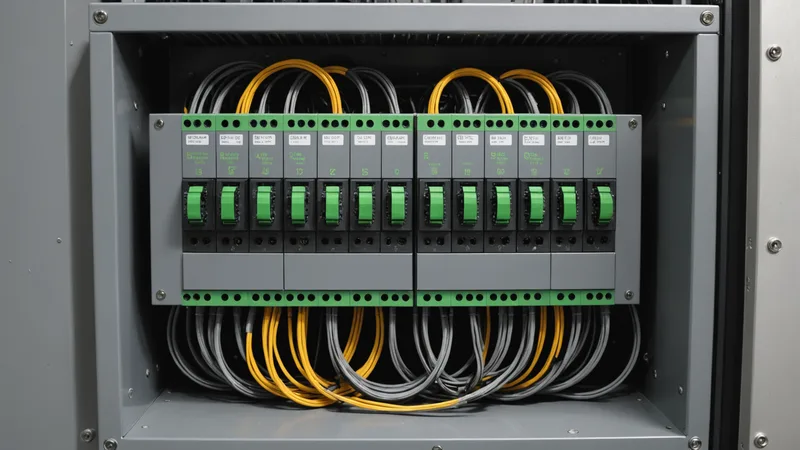
Modbus TCP is a protocol from 1999 that predates most of the people reading this article's professional careers. It has no built-in security, no data type system beyond 16-bit registers and coils, no discovery mechanism, and no concept of data freshness. It is also running in essentially every factory we have connected Sancho to. Not as a legacy holdover in one corner of the plant, but as a primary communication path for active production equipment.
The reason is simple: it works, it is cheap to implement, and every I/O device that has been manufactured for the past twenty years supports it. Trying to upgrade Modbus TCP out of a production facility is like trying to upgrade TCP/IP out of the internet. It will not happen on any timeline relevant to your career. So you learn to work with it effectively, which means understanding its specific annoyances before you design around them.
The Register Map Problem
Modbus has four data tables: coils (bit read/write), discrete inputs (bit read-only), holding registers (16-bit read/write), and input registers (16-bit read-only). This is the entire Modbus data model. There are no named variables, no structured data types, no versioning. There is just a flat array of 16-bit registers, and whatever meaning those registers have is defined by the device manufacturer in their device documentation.
The practical problem this creates: every Modbus device has its own register map. A Beckhoff I/O module, a SEW drive, a Banner sensor controller, and a custom conveyor controller all speak Modbus TCP, but they each have completely different register assignments. Register 40001 on a Beckhoff module might be a temperature setpoint. Register 40001 on an SEW drive might be a motor speed command. Register 40001 on the custom conveyor controller might be a status word with 16 bit-packed status flags. There is no interoperability at the semantic level, only at the byte-transport level.
This means every Modbus device integration requires reading the device manual, understanding the register map, deciding what data you actually need, and explicitly mapping those register addresses to meaningful names in your integration software. This documentation work is unavoidable and frequently under-budgeted on integration projects. We have seen projects where the Modbus register documentation for the various devices in a cell was incomplete, inconsistent, or available only in a non-English language requiring translation. Budget this time explicitly.
Multi-Register Data Types and Byte Order
Modbus registers are 16 bits wide. Any value that requires more than 16 bits, a 32-bit integer, a 32-bit floating point value, a 64-bit timestamp, occupies multiple registers. The Modbus specification says nothing about how multi-register values are ordered. Some devices store the high word (most significant 16 bits) at the lower address and the low word at the higher address (big-endian word order). Some do the opposite. Some use mixed byte order within a word. Some flip the byte order within each word relative to the word order.
This sounds like it should be well-documented by each device manufacturer, and it usually is, but the documentation is sometimes ambiguous. We have seen "big-endian" noted in a device manual that actually meant big-endian byte order within each word but little-endian word order across a 32-bit value. The only reliable way to verify byte order is to write a known test value (like 0x00010002) to a 32-bit register and read back both 16-bit registers to confirm the order.
In the Sancho Modbus connector, every multi-register mapping declares its byte and word order explicitly. The four common variants (big-endian / little-endian, with high-word-first or low-word-first) are all supported. The configuration forces you to specify the order, which catches the byte-order assumption bug at configuration time rather than at production time when your 32-bit motor position value is reading as a number that is wildly wrong but plausibly signed.
Coil Scan Rate and Stale Data
Modbus TCP is a polling protocol. The client polls the server at whatever rate the application requires. There is no subscription mechanism, no event notification, no way for the server to push data to the client when a register value changes. You get the data when you ask for it, and if you are not asking frequently enough, you may miss a transient event.
For coil states (bit-packed status flags), this creates a real-world problem for fast transients. If a robot outputs a "cycle complete" coil that is asserted for 50ms and then deasserted, and your Modbus poller is running at 100ms intervals, you will miss that pulse approximately half the time. This is a protocol limitation, not a configuration error. The fix is to use latching logic at the source: the device asserts the coil and holds it until the Modbus client explicitly writes a clear command. This requires that the device support latching behavior, which some do and some do not.
For anything where the risk of missing a transient state change is unacceptable, Modbus TCP is the wrong choice for that specific signal. Use a hardware interrupt input or a faster polling protocol. Modbus TCP is appropriate for process parameters, status words, and commanded setpoints that change on human-perceivable timescales. For machine-cycle coordination signals that change in sub-100ms windows, plan accordingly or use a different mechanism.
Where Modbus TCP Fits in a Modern Orchestration Stack
Despite its limitations, Modbus TCP has a well-defined role in a mixed-vendor cell. It is the universal language for devices that do not speak anything more capable: I/O expansion modules, drives, sensors, and peripheral equipment from manufacturers who could not justify implementing OPC-UA or EtherNet/IP on a $200 piece of hardware. It fills in the gaps in the protocol map that the more capable protocols leave open.
In Sancho's connector model, Modbus TCP functions as a generic I/O bridge. We use it to connect the peripheral devices in a cell that do not have dedicated connectors: custom test fixtures, pneumatic valve banks, conveyor drives, sensor controllers. The Modbus connector configuration accepts a register map definition that names each register address and specifies its type and conversion. The orchestration engine sees named, typed values, not raw register numbers. The translation happens once, at the connector layer, and the rest of the system is insulated from the Modbus-specific register addressing.
The one thing we never do with the Modbus connector is route cell sequencing handoffs through it. As described above, Modbus polling latency and potential for missed transients makes it unsuitable for real-time coordination. It is the sensor and peripheral interface; the coordination signals go through the PLC or direct robot interfaces where the timing guarantees are appropriate.
Read next: Bridging Siemens S7 Ladder Logic to MQTT Without Rewriting Your Program