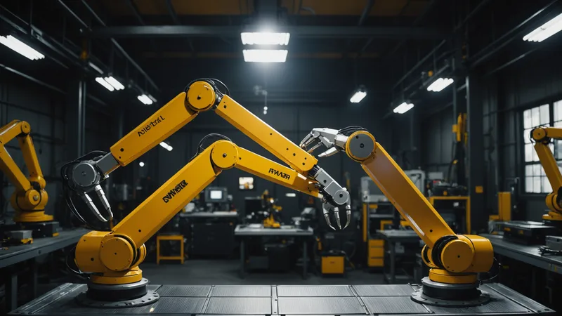
When a mixed-vendor workcell fails, the initial diagnosis almost always points at something vendor-specific: the KUKA arm threw an error, the FANUC controller went into fault mode, the UR program stopped mid-cycle. But in the majority of cases I have investigated, the vendor-specific symptom is not the root cause. The root cause is at the handoff layer between vendors, and the specific robot that stopped is simply the one that noticed the failure first.
This distinction matters enormously for how you fix the problem, and for how you design the cell to be more reliable going forward.
What the Handoff Layer Actually Is
Every multi-robot workcell has a sequencing problem: the robots need to know what each other is doing in order to proceed safely and efficiently. In a single-vendor cell, this is handled through the vendor's own system. A FANUC cell with two M-20iD arms can use the FANUC R-30iB's built-in zone management and PMC-coordinated interlock signals. Everything speaks the same language because everything came from the same vendor's integration team.
In a mixed-vendor cell, there is no shared sequencing system. A KUKA arm using RSI (Robot Sensor Interface) for external axis guidance has no built-in mechanism to coordinate with a UR arm using RTDE (Real-Time Data Exchange). The PLC is usually the bridge, but the PLC-mediated handoff introduces its own layers: a KUKA output bit has to set a PLC memory coil, which the PLC scan cycle reads and writes to an output, which goes to a UR digital input. At each step there is a latency, and the latency is not constant because PLC scan cycles are synchronous but robot I/O polling is asynchronous.
The handoff layer is the set of mechanisms, explicit or implicit, by which this cross-vendor coordination happens. It is almost always cobbled together from a combination of PLC ladder logic, hard-wired I/O signals, and vendor-specific robot programs that were written by different engineers at different times with different assumptions about what the other side would provide.
The Three Most Common Handoff Failures
After looking at a range of mixed-vendor cell failures, the same failure modes appear repeatedly. The first is a state assumption mismatch: Robot A moves to its ready position and signals a ready output, but Robot B is checking that output at a slightly different logical condition than what Robot A is asserting. Maybe Robot A is outputting "ready" as soon as its TCP clears a safety zone, while the original intent was for "ready" to mean "clear and at home position." This works reliably until there is a variation in the Robot A trajectory, at which point the ready signal fires earlier than expected and Robot B starts moving before Robot A is actually clear.
The second failure mode is error propagation gaps. In a vendor-uniform cell, an error on one robot can propagate to a hold state on all robots through a shared error management layer. In a mixed-vendor cell, error propagation depends on whatever interlock signals were wired up at integration time. If Robot A throws an E-stop because of a fault condition, does Robot B receive that E-stop via a hard-wired safety relay? Or does it depend on a software signal that Robot A may not be asserting in a fault state?
In one cell I examined, a KUKA arm going into protective stop was supposed to set a PLC output that would pause the UR cobot's cycle. The output was set correctly in the KUKA program for operator-triggered E-stops, but not for collision-detected protective stops (which triggered a different PLC code path that the integration engineer had not wired to the UR pause input). So a KUKA collision-detected stop would leave the UR cobot running, which then completed its next pick cycle and moved to a position that the now-stationary KUKA was supposed to have already vacated. The result was a zone intrusion alarm from the safety scanner, which shut down the entire cell.
The third failure mode is timing drift. Each robot controller runs on its own clock. Handoff sequences that depend on timing windows, not explicit state signals, will drift over time as clocks diverge and as firmware updates change the precise timing of signal transitions. A handoff sequence that worked fine at commissioning may start failing six months later because the KUKA RSI cycle time was adjusted slightly in a firmware update, pushing a signal transition outside the timing window the UR program was designed around.
Why This Is Not the Robot's Fault
None of these failure modes are caused by the robots malfunctioning. Each robot is doing exactly what its program tells it to do. The failure is in the layer between the robots: the assumptions embedded in the coordination logic, the incomplete error propagation wiring, the timing dependencies that were not made explicit at integration time.
This is why blaming the symptom (the KUKA threw an error) rather than the cause (the handoff coordination logic had a gap in its error propagation) leads to the wrong fixes. Adding a more aggressive KUKA error retry loop does not fix an underlying handoff gap; it may actually make it worse by masking the error condition longer before the cell enters a safe halt.
What a Good Handoff Architecture Looks Like
A well-designed handoff layer has three properties: explicit state assertions (every "I am ready for handoff" signal maps to a precisely defined robot state, not an assumption about trajectory timing), complete error propagation (any fault on any device causes a coordinated halt of all devices through mechanisms that are tested at commissioning), and no implicit timing dependencies between robots from different vendors.
The third property is harder than it sounds. It means replacing timing-window coordination with explicit state-acknowledge sequences. Instead of "Robot A moves for T milliseconds then signals ready, Robot B starts after T plus delta milliseconds," the correct pattern is "Robot A signals ready only when it has completed its motion and received a sensor confirmation, Robot B moves only after explicitly acknowledging the ready signal and waiting for a clear-to-proceed acknowledgment from the cell controller."
Sancho's cell sequencing model is built around this principle. Handoff rules in a cell map are expressed as state-condition logic: step A is complete when condition X is true (where X is a verified sensor or controller state, not a timer). Step B does not start until the orchestration layer has confirmed condition X and issued an explicit start command. This eliminates the timing-window dependency class of failures, which in our experience accounts for roughly a third of all intermittent mixed-vendor cell stops.
The remaining two failure classes, state assumption mismatches and incomplete error propagation, require explicit specification and testing at commissioning. No software layer eliminates those without clear integration requirements. But at least with explicit state-based coordination, the cell map documents those requirements in a form that a new engineer can read and verify, rather than having them live implicitly in the timing of PLC scan cycles and robot trajectory speeds.
Read next: Three Commissioning Mistakes When Mixing KUKA and Universal Robots in One Cell