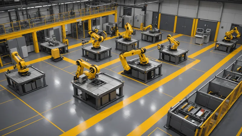
Before you can understand where integration problems come from in a mixed-vendor cell, you need a clear model of what is actually in the cell and what each component is responsible for. This sounds basic, but in practice the control architecture of a production cell is often only partially documented, and the undocumented parts are frequently where the integration problems live.
This post walks through the layers of a typical mixed-vendor cell from the physical layer upward, with an emphasis on the communication boundaries between layers and the coordination responsibilities at each boundary.
Layer 1: The Robot Controllers
Each robot in the cell has its own controller: a dedicated computing unit that runs the robot's control software, manages the servo drives and joint motion, executes the robot program, and provides external communication interfaces. This controller is fundamentally a real-time system. Its primary job is to execute motion commands at the millisecond timescale, and it is designed around that constraint.
The external interfaces on a robot controller are designed primarily for single-vendor communication. KUKA's KRC4 controller provides RSI for sensor-guided motion and KLI (KUKA Line Interface) for fieldbus I/O. FANUC's R-30iB provides its Robot Interface protocol for program control and FANUC FOCAS2 for CNC data. ABB's IRC5 provides RAPID socket connections and EGM for external guidance. Universal Robots provides RTDE and their Primary/Secondary/Real-Time interfaces. None of these are designed to natively interoperate with another vendor's controller, because none were designed with the assumption that they would share a cell with a non-KUKA or non-FANUC or non-ABB controller.
This is not a design flaw. It is a consequence of designing for a specific use case. The integration challenge arises when multiple of these purpose-built systems need to act as a coherent unit.
Layer 2: The PLC (Programmable Logic Controller)
In most production cells, a PLC is the coordination hub. It handles the safety interlock logic (E-stop chains, light curtain signals, door interlocks), the I/O that does not belong to any single robot (part-present sensors, conveyor triggers, clamp actuators), and in many cells the sequencing logic that coordinates the robots via digital I/O signals.
The PLC operates differently from the robot controllers. It runs a scan cycle, typically 1ms to 10ms, that reads all inputs, executes the program logic, and writes all outputs in sequence. This is deterministic and reliable for I/O-based coordination, but it introduces a structural latency: any event detected on a digital input will not be reflected in the output logic until the next scan cycle. For most sequencing coordination this latency is acceptable. For anything that requires sub-millisecond coordination, the PLC is the wrong coordination mechanism.
The PLC is also the translation point between the fieldbus world (EtherNet/IP, Profinet, Modbus TCP connecting to sensors and actuators) and the robot communication world. A robot arm output that needs to trigger a conveyor motor typically goes through the PLC: robot sets an output bit, PLC scan reads that bit, PLC logic evaluates the condition, PLC output activates the motor drive. This chain works, but it is multiple hops, each with its own latency contribution.
Layer 3: The Cell Controller or Orchestration Layer
Above the PLC, many cells have what is loosely called a cell controller: an industrial PC or edge device running software that coordinates the overall production sequence, manages production orders from the MES, handles alarm escalation, and provides visibility into the cell state for operators and supervisors. This layer is where the "intelligence" of the cell lives in the sense of process decisions, as opposed to the lower-level motion control that happens in the robot controllers and PLC.
In practice, this layer is frequently underpowered or absent. In cells we have examined, the most common situation is that the PLC is doing double duty: both the low-level I/O coordination work it was designed for and the cell-level sequencing and state management work that belongs at a higher layer. This creates brittle ladder logic that is hard to maintain and hard to extend, because adding any cell-level behavior requires adding ladder logic to an already complex PLC program.
Sancho lives at this layer. The orchestration engine runs as a process on an industrial PC connected to the cell network. It manages the cross-robot coordination logic, leaving the PLC free to handle the I/O and safety logic it was designed for. The cell map defines the sequencing rules in a configuration format that can be read, understood, and modified by an engineer who was not involved in the original integration.
Layer 4: The MES Interface
Above the cell controller is the manufacturing execution system, which manages production orders, tracks part genealogy, and provides production reporting. The MES needs information from the cell: cycle counts, alarm events, production rates, part quality data. The cell needs information from the MES: production orders, job sequences, operator instructions.
This interface is where IT and OT meet, and it is frequently the most problematic boundary in the stack. The MES is typically an enterprise IT system that expects to communicate via standard protocols (OPC-UA, REST, database connections) on standard IT network infrastructure. The cell-level systems were designed for industrial network infrastructure with different latency and reliability characteristics. The translation between these two worlds requires explicit design at the boundary.
A common failure mode: the MES expects production data in near-real-time (under a second from event to database record), but the path from the robot controller to the MES database involves the PLC scan cycle, the cell controller polling interval, an OPC-UA server publish interval, and a MES polling interval. The total latency can easily be 2 to 10 seconds, which is invisible during integration testing (where each step is checked individually) and only surfaces in production when time-correlated analysis shows that event timestamps in the MES are seconds off from the actual machine events.
Where the Integration Surface Lives
The integration surface in a mixed-vendor cell is not at any single layer. It is at every boundary between layers, and it is at every boundary between vendors within a layer. The KUKA-to-PLC boundary. The UR-to-PLC boundary. The PLC-to-cell-controller boundary. The cell-controller-to-MES boundary. Each boundary requires explicit design of the communication protocol, the data model, the latency expectations, and the failure handling.
The cells that run reliably are the ones where these boundaries are explicitly designed and documented, not assumed or left implicit. Before wiring anything in a new cell, mapping out these boundaries and explicitly answering "what crosses this boundary, in which direction, at what rate, and what happens when it fails" is the most valuable time investment in the entire project.
Read next: Robot-Agnostic Orchestration and the Flexible Manufacturing Case